Wow. The world is getting back to work and we are feeling the global demand for testing equipment, service and support. CTW has never been busier than we are right now and that continues to cement our place in the Testing world, the racing community and the 2-wheel arena. We continue to expand our product line, our software features and our markets world wide.
CTW in China.
CTW recently signed an agreement with Shenzhen Lynag Technology Co., Ltd.
They will represent CTW in China exclusively and from all initial communications the demand is growing. With representatives now in Japan, Australia and China CTW anchors itself across the globe. Now that we have increased our markets across the globe, we want to share new models, features and software coming soon.
Longer stroke machines.
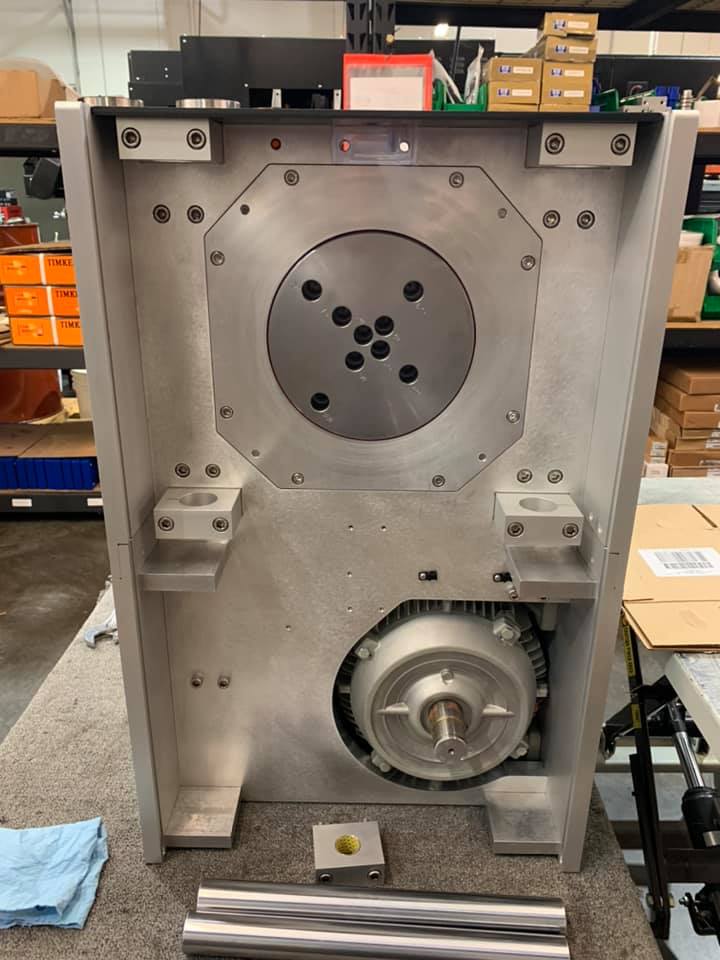
First view of the new Big Stroke RD10 and RD7.5 machines.
A new peak stroke of 160 mm.
Front view of the larger crank-head
CTW has increased the peak available strokes of the RD7.5 and RD10.
These new machines will have a peak stroke of 160mm. This will also increase the peak velocity up to 3.0 m/sec.
Final specifications and performance will be added once we get the first one up and running.
** Metric standard strokes: 20-25-40-50-75-100-125-150-160 mm
** Available in the 7.5 and 10HP models
Digital I/O capacity.
Digital IO on the LA series: using (2) digital IO signals, the User will be able to apply a current to open / close a valve(s) in a damper. This new optional feature will meet a unique and growing market as more and more dampers have electric valves integrated in their system.
Now, using CTW Probe, the User can command the signal at various times during the Test with simple commands.
CDC – Continuous Damping Control – in development
Once the digital I/O is incorporated in the CTW Probe software for the LA series, we will begin to work out how to add a software analysis feature to be able to report on the response of the damper, as a system.
With the plethora of damper systems integrating valves that are active, one of the fundamental first steps in using them is to quantify the response time. Beyond turning a valve on/off is the force response from this event.
CTW is working with two partners to create a Testing procedure to activate a valve and then report the response time(s) accordingly. The goal is to produce data that can track the time it takes from activation to a target force change.
Exciting times ahead.
Future arguments of responsiveness will now be based on data and milli-seconds rather than guessing.
Analog out capacity.
Analog out on the LA series: using up to (2) analog outs, the User will be able to apply a voltage to a given device. In our first offering, we
will add the option of a pneumatic side loading mechanism capable of applying a load up to 1000 N. As we know dampers in the real world experience off axis loading causing increased friction and wear. Now CTW customers can add a side load during the Test to quantify these affects.
The CTW side loading mechanism is a pneumatic addition. It activates on Command and can be changed between Test speeds.
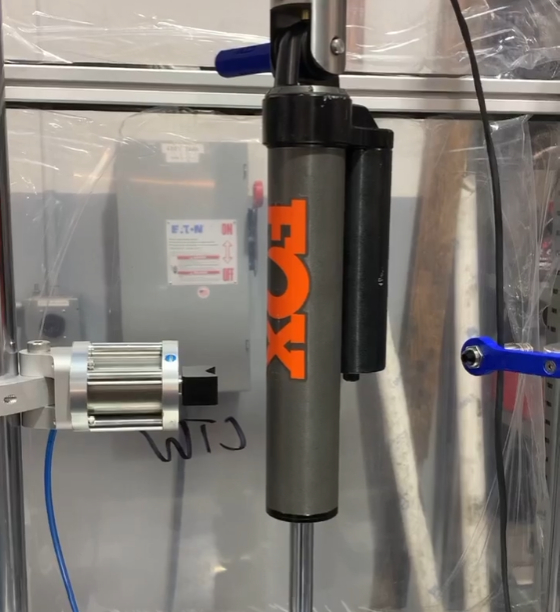
Validation and Probe Advanced features software
A future release of CTW Probe will include an advanced package for Users that need more than the basic software and graphs. This will be included in this advanced package at an additional cost. This software will begin to include features outside the normal version of Probe that will allow Users do more, get more and test more.
CTW Validation will allow the User to build Validation files, save them and apply them at any time to any data, new or old. The User can edit the tables, change the min/max, etc….
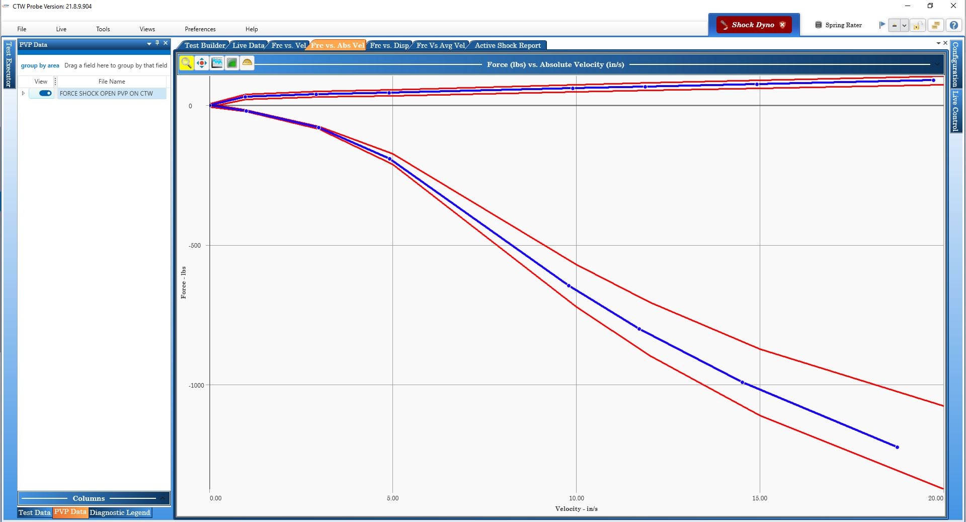
Validation screen shot
Variable sine wave motion.
Thanks to direct customer feedback and input, CTW has reinvestigated the drive profile created by the Variable sine wave feature. When joining a compression wave with an extension wave of a different velocity profile (and the resulting acceleration) there can occur a moment of “jerk” the technical term for change in acceleration. This can, and has, caused a reaction from the damper that can best be described as “not real”. CTW has developed a better motion at the transition phases of the Test wave form. This will have far reaching effects and will help CTW as well as Roerhig customers alike. Truly a story of learning a new method and applying it to our products.
Triangle waves.
We have also been investigating triangle wave motion and will be adding to the Probe software manual as well as a short pdf to be released on the website to continue to evolve the User understanding of these wave forms.
The CTW Probe software allows for limiting the Acceleration of the Triangle wave and the use of this feature can allow for a better transition in each direction of motion.
With little or no limitation of the accel / decel at the turn around phase, outside variables can be introduced into the damper and cause for data to be compromised.
Further, we will add more insight into gain tuning for triangle waves to maximize the available time during the critical constant velocity phase of the test. Look for this to be added in the near future.
As a simple insight, we can share a screen shot showing the various Accel Limits and the reaction of the LA system.
In the screen shot below of a Force v Displacement graph, the same damper and the same Test are run to show the effect of limiting the Accel Rate in the Test. This happens for a variety of reasons, all adding together to influence your damper and the resulting data.
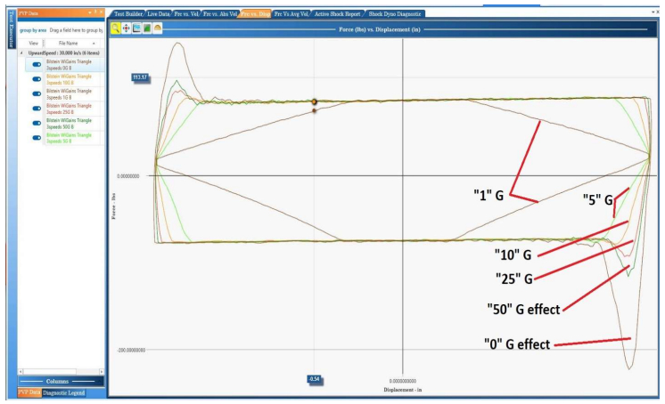
ctwautomation-blog-force-v-displacement
Force v Displacement from a series of Triangle waves
On the horizon we are in the early stages of developing:
HIL (hardware in the loop) testing… 4 LA’s at one time with each running a “corner’ car simulation on the damper.
Low “noise” machine (under 50 dB) to allow for “listening” to the internals of the damper as part of the tuning. Making the actuation as quiet as possible so that the damper can be “heard”.
CDC (no, not that one) package that will allow the user to test electric valve response (previously mentioned). Turning a damper valve on is part of the equation, knowing when its effect is shown in the damper is just as important.

